GeoSearchesFull-service geophysics · Nationwide & worldwide · Est. 2000
Nothing under your site should be a surprise. Design on measurements, not assumptions.
We run non-intrusive geophysics — GPR, electromagnetics, resistivity, seismic, magnetics, LiDAR and more — so you know what’s in the ground before you dig, core or pour.
Concrete scanningUtility locating & SUEStorage tanksVoids & sinkholesDrill location clearanceAbandoned mine workingsAbandoned oil & gas wellsSeismic site classificationDrone LiDAR & thermographyTill & colluviumWeathered shaleSandstoneLimestone markerShaleCoal seamBedrockUnconformity, normal fault and water table shown
45 yearsOf field experience
NineInstrument families
FourContinents surveyed
Est. 2000Twelve states served
Methods & equipment
Nine families of instrument, above ground and below
Each measures a different physical property of the ground — dielectric contrast, conductivity,
elastic velocity, magnetic susceptibility, density, thermal conductivity. Combining two or three is
often what turns an ambiguous anomaly into an answer. Instruments are owned and operated in-house,
not hired in for the day.
01 / RADAR
Ground-penetrating radar
Dielectric contrast imaging from millimeter resolution in concrete to tens of feet in favorable ground.
1.6 – 2.6 GHz concrete antennas
400 MHz utility antennas
100 – 200 MHz deep antennas
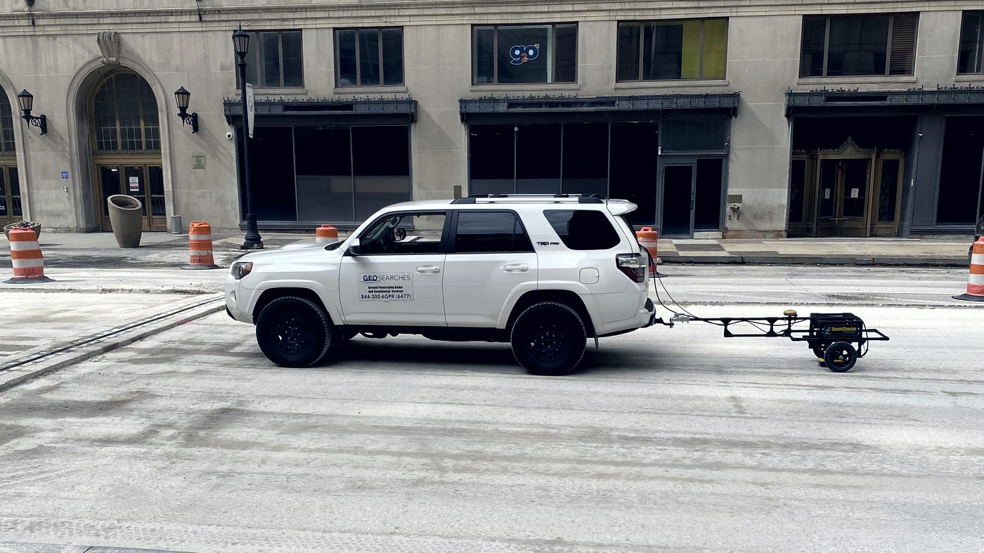
Vehicle-towed antenna for roads, decks and runways
How quickly the ground carries heat away decides how much current a buried cable can carry.
Assume it and the feeder is either undersized or paid for twice.
Larger-area work where the target isn't a utility and the records don't exist.
Underground storage tanks
Buried drums and waste cells
Abandoned foundations
Landfill extent and depth
Sinkholes, voids & mine workings
Karst & dissolution features
Graves and archaeology
Abandoned oil & gas wells
A pile driven into a forgotten casing is a very bad day. Wells sunk before anyone kept records
appear on no map — and solar and wind sites cover a great deal of ground in exactly the country
where those wells were drilled.
Where a building loses heat, takes water or hides a fault, thermal imaging finds it without
opening anything up. Interiors and exteriors, at ground level or flown.
ASCE 7-22 changed the basis of this work. Site class is now determined by shear-wave velocity
alone; standard penetration resistance and undrained shear strength are no longer an acceptable basis.
Three classes were added — BC, CD and DE — and Class A and B can only be assigned from velocity
measured on site. If nobody measures, the structural engineer designs to the conservative default,
and on a large slab that shows up directly in steel tonnage.
We measure Vs30 — the harmonic mean shear-wave velocity over the top 100 ft (30 m) —
without a borehole, usually in a single day on site. MASW uses an active source and Rayleigh-wave
dispersion for resolution through the shallow section. ReMi is passive, reading ambient traffic
and plant noise, so it works on loud urban and industrial sites and reaches deeper. Run together they
extend the dispersion curve at both ends and better constrain the profile.
AHard rockSite measurement
BMedium hard rockSite measurement
BCSoft rock2,100–3,000 ft/s
CVery dense sand / hard clay1,450–2,100 ft/s
CDDense sand / very stiff clay1,000–1,450 ft/s
DMedium dense sand / stiff clay700–1,000 ft/s
DELoose sand / medium stiff clay500–700 ft/s
EVery loose sand / soft clayBelow 500 ft/s
FSite response analysisPer ASCE 7-22 Ch. 21
Deliverable: shear-wave velocity profile, Vs30, and site class to
ASCE 7-22 / IBC in a signed report for the structural engineer and the permit set. Data center
programs are the busiest source of this work right now — large footprints, fast schedules, and a
seismic design that governs a great deal of steel.
Before a rig sets up, we clear the footprint. Boreholes hit things — services, tanks, old
foundations, mine workings — and the cost of finding out with a drill string is never just the drill string.
Utility clearance at the collar
Full rig footprint & access route
Tanks, drums & buried steel
Old foundations & obstructions
Voids & abandoned workings
Marked out to APWA code
Geotechnical & environmental bores
Written clearance record
ASCE 38 · Subsurface utility engineering
What non-intrusive means for your deliverable
Utility information comes in four quality levels. We produce three. The fourth needs a vacuum truck.
QL-DWe provide
Existing records and utility owner information, compiled and reconciled.
QL-CWe provide
QL-D plus surveyed above-ground features — manholes, valve boxes, meters.
QL-BWe provide
Geophysical designation of horizontal position, with depth where the method supports it.
QL-ARequires excavation
Plan and elevation from exposing the utility. Outside our scope — we designate the dig points.
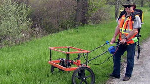
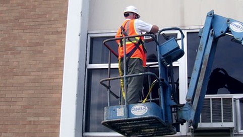
Utility survey, closed downtown carriageway. Towed GPR behind the survey vehicle.Low-frequency antenna on a rural verge. Deeper section, coarser resolution.Facade and envelope inspection from a boom lift.
What you receive
The survey is the method. This is the product.
Marks on the ground wash off. What you keep is the drawing — every line attributed to a
quality level, every depth stated, and the one thing you actually asked answered on its face.
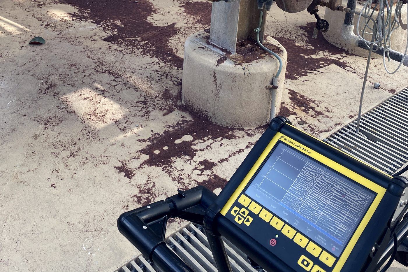
Acquisition inside a live plant. The radargram on the screen is the raw record —
what follows is what it becomes.
Every run carries size, material, quality level and depth. Solid lines are QL-B —
designated geophysically. Dashed lines are QL-D — records only, never walked. Anything we could not
resolve is drawn as unlocatable rather than left off, because a gap on a drawing reads as clear ground.
The proposed core landed on a post-tension tendon at 2.9 in cover. Cutting it would have
been expensive and possibly dangerous. The plan clears a relocated position 23 in away, dimensioned
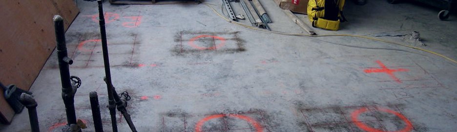
off the column grid, with the nearest steel and a maximum bit diameter stated.The same information on the slab itself — steel marked out, cleared core positions
ringed. The drawing is what survives after the paint has gone.
Drawings are issued as PDF and, where the project needs it,
as CAD or GIS for direct import. Both examples are illustrative — real deliverables carry the site,
the date, the instrument and the operator.
Case study 01
A wartime runway on a dissolving island
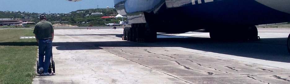
Antigua is karst. The limestone beneath it dissolves, and where it dissolves it leaves voids that
give no warning at the surface until something drops through.
Void and sinkhole survey of the runway, Antigua — worked around live cargo traffic.
LocationAntigua, Caribbean
SectorAviation — general & cargo
PeriodMid-2010s
TargetVoids & developing sinkholes
MethodGPR, low-frequency antenna c. 80 – 250 MHz
AccessNon-intrusive. No closure, no coring
OutcomePavement repaired and redesigned
The site
A runway laid during the Second World War, still carrying private and cargo traffic seventy years
later. Sound pavement on soluble rock is a particular kind of problem: the surface stays intact
while the ground under it goes hollow, and the first symptom is usually the failure itself.
The constraint
An operating airfield. Coring a grid across the pavement was never realistic — and coring only
ever tells you about the holes you drill. Between them, the ground is an assumption.
The method
Ground-penetrating radar with a low-frequency antenna working across roughly 80 to 250 MHz.
Low frequency trades resolution for penetration, which is the right trade when the target is a
void meters down rather than rebar in a slab. Continuous survey lines along and across the
pavement gave coverage between the points a drilling program would have sampled.
The outcome
Voids and developing sinkholes were located and mapped beneath the pavement. The runway was
repaired and redesigned on the strength of the survey rather than on assumption — and stayed open
while the work was scoped.
The same problem sits under any pavement, slab or yard built on soluble
ground: limestone, gypsum, old workings. The instrument changes with the site. The argument
doesn't — you cannot core your way to a void map.
Case study 02
The men outside the fence
A Confederate officers' prison stood on Johnson's Island in Sandusky Bay. The men who died
there were buried in thin soil over bedrock, under wooden headboards that did not last.
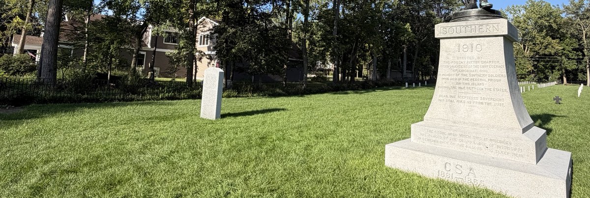
Confederate Stockade Cemetery, Johnson's Island — the 1890 markers, the 1910 monument, and the two stones set in 2003.
Outcome267 sets of remains located Cemetery boundary realigned
The site
Around twelve thousand Confederate officers passed through the prison camp during the war.
Those who died there were buried beside it, in ground where bedrock sits close enough to the
surface to prevent burial at the customary depth. The first markers were wooden headboards. By
1890, when citizens of Georgia paid for 206 marble headstones, the original positions were
already a matter of inference.
The constraint
You cannot excavate to find graves. Not here, not anywhere. The question was where the burials
actually lay, and the only acceptable answer was one that disturbed nothing — which left exactly
one class of method.
The method
Ground-penetrating radar, run across the cemetery and deliberately beyond the fence line
rather than only within it. Graves are a subtle target: the signature is the disturbed soil of
the shaft and the contrast between backfill and undisturbed ground, not the remains themselves.
Shallow bedrock helps as much as it hinders, because a grave cut into rock leaves a boundary the
radar can follow.
The outcome
267 sets of remains were located — sixty-one more than the 206 markers accounted for,
and found both inside the iron fence and beyond it, in ground that had not been treated as part
of the cemetery for well over a century.
The boundary was realigned to bring them inside it, and the headstones were replaced against
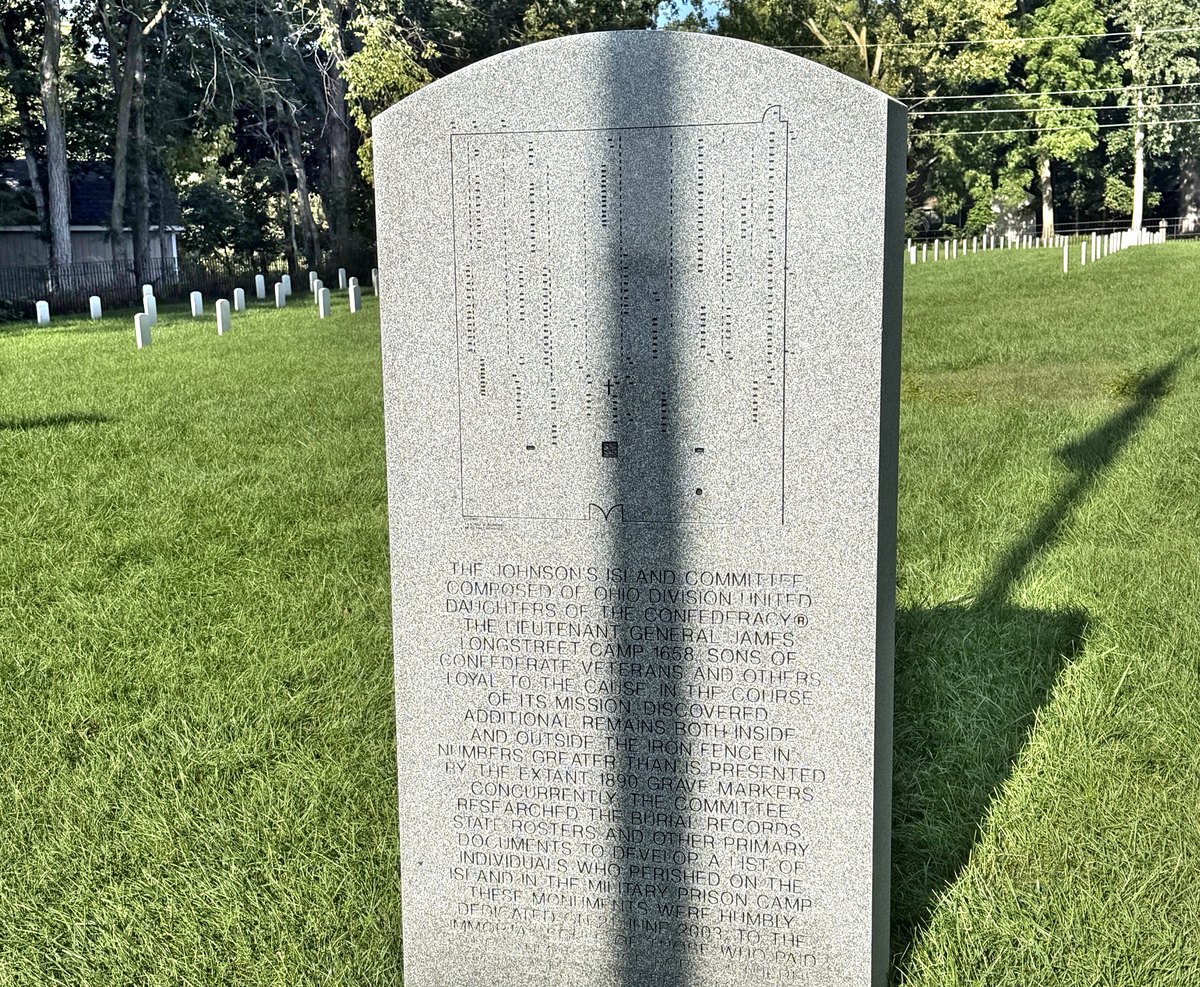
the survey rather than against the old assumption. Two granite monuments were dedicated on
21 June 2003. One carries the map produced from the survey. The other records how the work was
done, in a sentence that reads: two hundred sixty-seven sets of remains of those who died in
the prison camp from 1862 to 1865 have been located through the use of non invasive ground
penetrating radar.
The survey map, cut into granite at the cemetery — dedicated 21 June 2003.
Where excavation is unacceptable rather than merely inconvenient —
cemeteries, consecrated ground, archaeology, anywhere a mistake cannot be undone —
geophysics is not the cheaper option. It is the only one. The deliverable here outlived the
invoice by some margin.
ASCE 7-22 · IBC · V̄s30
Seismic site classification, measured rather than assumed
ASCE 7-22 changed how this works. Site class is now determined by shear-wave velocity alone —
blow counts and undrained shear strength are no longer an acceptable basis — and three new classes
were added between the old ones. If nobody measures the velocity, the structural engineer designs
to a conservative default.
SAMPLE DELIVERABLE / MASW + ReMi SHEAR-WAVE VELOCITY PROFILEASCE 7-22 SITE CLASS BANDS
Illustrative profile. V̄s30 is the harmonic mean shear-wave velocity over the
top 100 ft (30 m) — not the arithmetic average — so soft near-surface layers weigh heavily on the result.
AHard rockSite measurement required
BMedium hard rockSite measurement required
BCSoft rock2,100 – 3,000 ft/s
CVery dense sand / hard clay1,450 – 2,100 ft/s
CDDense sand / very stiff clay1,000 – 1,450 ft/s
DMedium dense sand / stiff clay700 – 1,000 ft/s
DELoose sand / medium stiff clay500 – 700 ft/s
EVery loose sand / soft clayUnder 500 ft/s
FSite response analysisPer ASCE 7-22 Ch. 21
Why it is suddenly busy
Data center programs are driving most of this work — very large footprints, compressed
schedules, and a seismic design that governs a lot of structure. The same requirement lands on
warehousing, manufacturing, healthcare and any project reaching for a permit under the current code.
Two of the nine classes can only be reached by measuring velocity on site. Without data, the
default assumption applies; with it, the engineer designs to what the ground actually is.
How we measure it
MASW — active source, multichannel analysis of surface waves. Rayleigh-wave dispersion
inverted to a shear-wave velocity profile. Strong resolution through the shallow section.
ReMi — refraction microtremor. Passive, using ambient traffic and plant noise, so it
works on live industrial and urban sites and reaches deeper than an active source alone.
Run together — the two extend the dispersion curve at both ends and give a
better-constrained profile than either on its own.
Deliverable: shear-wave velocity profile, V̄s30, and site class to
ASCE 7-22 / IBC in a report for the structural engineer and the permit set. No borehole, no coring,
nothing left in the ground — most sites are a single day.
The other number a data center asks for
Soil thermal resistivity
Site class sizes the structure. Thermal resistivity sizes the power. Both get asked for at the
same stage of a data center program, and both are measurements rather than assumptions.
Every buried feeder and duct bank
depends on the ground around it carrying heat away. Where it can't, the cable runs hot and its
ampacity falls. Design on a guessed value and you either undersize the feeder or pay for copper
you never needed — and on a campus with megawatts of underground distribution, that margin is
not small.
Resistivity rises sharply as soil dries,
so the design case is the dry case. We measure across moisture content to produce the dry-out
curve, not a single fair-weather number.
Method — thermal needle probe to IEEE 442. A line heat source is energised and the
rate of temperature rise gives the thermal constants of the surrounding material.
Where — in situ at actual burial depth along the cable route, plus laboratory testing
of native soil and any engineered thermal backfill.
Note — the needle probe is inserted into the soil. It is the one test we run that is
not wholly non-intrusive, and we say so rather than stretch the word.
Deliverable: thermal resistivity in °C·cm/W and K·m/W by
location and depth, dry-out curves, and a recommendation on whether native soil will serve or
engineered backfill is required.
The company
Looking through the past to build the future
The company dates from 2000. The experience behind it runs to forty-five years in
geophysics, nationally and internationally, on four continents and counting.
We are a full-service geophysical company. That means we are not tied to one
instrument and one answer — we select the method from the question, the target depth and the ground,
and combine methods when a single dataset would leave the result ambiguous.
Almost every survey is non-intrusive, and all are non-destructive. Nothing is
excavated, nothing cored, nothing left in the ground. The one exception is thermal resistivity
testing, which inserts a slim needle probe and withdraws it on completion. Knowing the ground
before you commit to a design is cheaper than discovering it mid-project. That has been the whole
argument since 2000, and it has not needed updating.
Sister company
Terradocs
Terradocs turns project details into a sendable proposal, scope or safety document —
standards-referenced, priced from your own rate table, and carrying the limitations language
that protects your firm.
Data acquired across North America, Europe, Africa, the Middle East, the Far East and Latin America.
Get a survey scoped
Call first. It's faster.
Tell us the site, the ground and what you're
trying to find. Most scopes get quoted on the phone, and the right method usually becomes obvious in that call.