Home › Geophysical services › Bridge deck condition surveys
Applications
Bridge deck condition surveys
A map of where a deck is deteriorating, across its whole area, collected from a vehicle rather than on hands and knees. Repair quantities come from data covering every square foot, not from a sounding of a few lanes.
What the survey measures
The method is the one set out in ASTM D6087. A radar pulse travels down through the overlay and the concrete and reflects strongly off the top mat of reinforcing steel. How strong that reflection is depends on what the energy passed through on the way. Concrete that is wet, cracked or contaminated with chloride — the conditions that go with corroding steel and developing delamination — is electrically lossy, and it weakens the return.
Measure that reflection at every bar across the whole deck, correct it for the depth of the steel, and the weak areas stand out as a plan. That plan is the deterioration map. The same data also gives the concrete cover over the top mat and the thickness of any asphalt overlay, everywhere it was collected.
Why radar rather than sounding alone
Chain drag and hammer sounding find delaminations by ear. They need the lane closed and the surface bare, they cannot hear through an asphalt overlay, and they only find a delamination once it has formed. The result depends on who was listening.
Radar reads through an overlay, records every trace so the result can be checked, and picks up deteriorating concrete before it has cracked loose. Because the data are positioned, the same deck surveyed again in five years shows how the deterioration has moved — the difference between a repair estimate and a maintenance programme.
None of that makes sounding, half-cell potential or cores redundant. They measure different things, and a deck survey is at its strongest when a handful of cores or sounding results are used to calibrate what the radar amplitude means on that particular structure.
How it is run
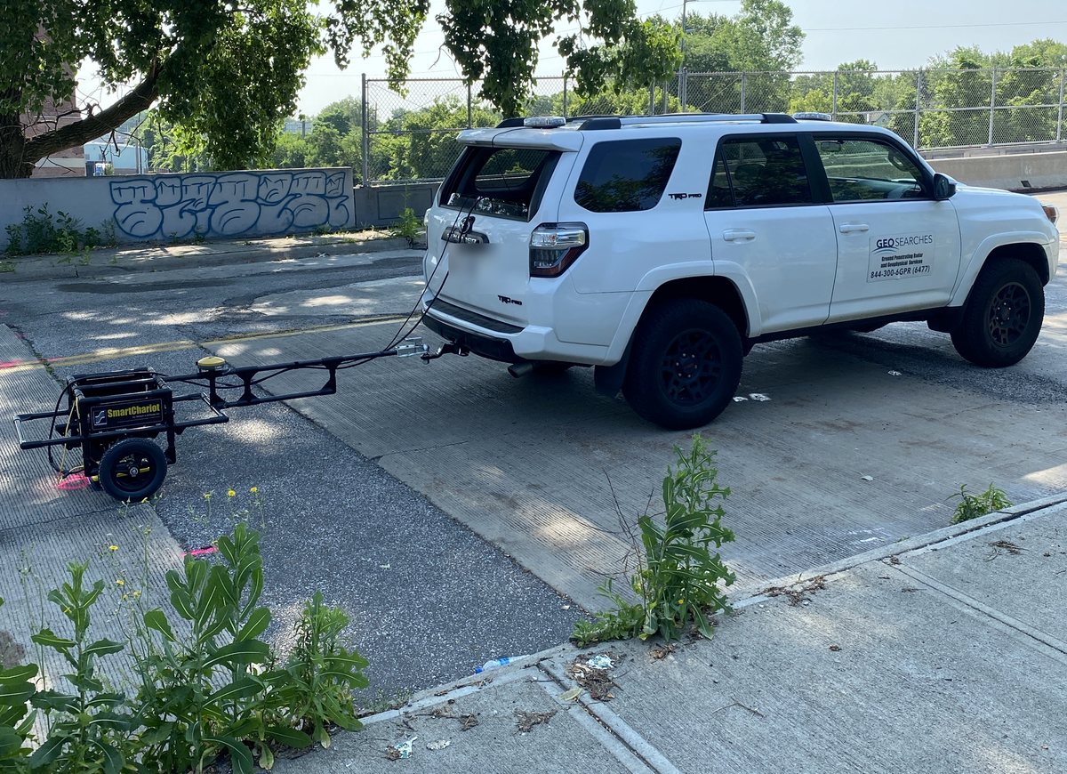
The antenna is towed behind a vehicle at survey speed and positioned by GNSS rather than by odometer. The deck is covered by running adjacent lines at a set spacing, chosen so the deterioration map is resolved at the scale the repair will be priced at. Towing rather than pushing is what makes a full deck practical, and it shortens the time a lane is occupied considerably compared with sounding, though what traffic control is needed is always the bridge owner's decision, not ours.
Decks are surveyed dry. Standing water, recent rain and fresh de-icing salt on the surface all depress the reflection and would show up as deterioration that is not there, so the survey is timed to the weather rather than to the calendar.
What it will not tell you
Radar amplitude is an indicator, not a measurement of corrosion. A low reading means the concrete above the steel is behaving the way deteriorating concrete behaves. It does not prove the steel is corroding, and it cannot put a number on section loss.
The map is relative to the deck it came from. Congested or unusually deep reinforcement, thick or variable overlays, waterproofing membranes and some concrete mixes all affect the reflection, and each has to be accounted for rather than ignored. Radar is also not the best tool for imaging a delamination plane directly — under the right daytime heating, infrared thermography often shows delaminations more clearly, on a quite different physical basis. Where the two agree over the same area, that agreement is considerably stronger evidence than either alone.
Every report states which of these applied on that deck.
Who commissions it
- Bridge owners and their consultants — state, county and municipal decks, ahead of a rehabilitation design or as part of a condition programme.
- Bridge inspection and design firms — who need quantities for a repair package rather than an estimate.
- Parking structure owners — elevated decks in garages see the same salt, the same corrosion and the same question about how much needs repair.
- Contractors — verifying overlay thickness or cover depth on new or rehabilitated work.
Equipment and capability
- Vehicle-towed antenna at survey speed
- High-frequency antennas for concrete and overlays
- GNSS positioning on every trace
- Deterioration mapping from top-mat reflection amplitude
- Concrete cover and asphalt overlay thickness mapping
- Infrared thermography as a corroborating method
What you receive
A plan of the deck showing the deterioration map, classed and shaded so the poorest areas are obvious, with the area in each class so repair quantities can be priced. Cover depth and overlay thickness maps from the same data. The radar data itself, so the interpretation can be checked rather than taken on trust. A plain statement of the conditions on the day and the limits that applied. CAD and GIS layers on request, so the results sit on the bridge drawings rather than beside them.
Ask before you commission
Tell us the target, the ground and the constraint and we will say whether this method answers it, whether it needs a second method alongside, or whether something else entirely is the better route. That conversation is free and it is usually short.