Home › Geophysical services › Ground-penetrating radar
01 / Radar
Ground-penetrating radar
The highest-resolution picture available of the first few feet of ground, and the only geophysical method that images inside a concrete slab. Radar is where most of our work starts.
What it measures
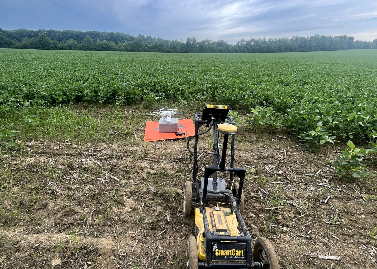
A GPR antenna radiates a short electromagnetic pulse into the ground and records what comes back. Energy reflects wherever the dielectric permittivity changes — at the boundary between concrete and air, soil and pipe, fill and undisturbed ground, rock and void. The time the echo takes to return, converted using a velocity measured on the site itself, gives the depth.
What that means practically is that radar sees contrast, not material. A PVC pipe full of water and a PVC pipe full of air are different targets. A rebar mat in dry slab is obvious; the same mat under a wet screed may not be. Reading a radar section is largely a matter of knowing which ambiguities matter on the job in hand.
Frequency decides everything
There is no single GPR. Antenna frequency trades resolution against depth, and the choice is made against the target, not against a price list:
- 1.6 – 2.6 GHz — concrete. Millimeter resolution, roughly the top 18 in. Rebar, post-tension tendons, conduit, slab thickness, voids beneath slab.
- 400 MHz — the utility workhorse. Typically 6 – 12 ft in favorable ground, less in clay. Pipes, ducts, tanks, structures, disturbed ground.
- 100 – 200 MHz — geology and deep targets. Tens of feet in sand, gravel, dry rock and karst limestone. Voids, bedrock, stratigraphy, mine workings.
Where the target range is uncertain we run two frequencies over the same lines rather than guess. It costs a little more field time and removes an entire category of missed target.
What it will not tell you
Radar is attenuated by conductive ground. In heavy wet clay, saline soil or over reinforced slabs with dense top mats, useful penetration can fall to a foot or two — occasionally to nothing. That is a property of the site, not of the equipment, and no amount of processing recovers signal that never returned.
When we expect that, we say so before mobilizing and propose electromagnetics or resistivity alongside or instead. A radar survey sold into ground that cannot support it is the most common way these projects go wrong.
How we collect it
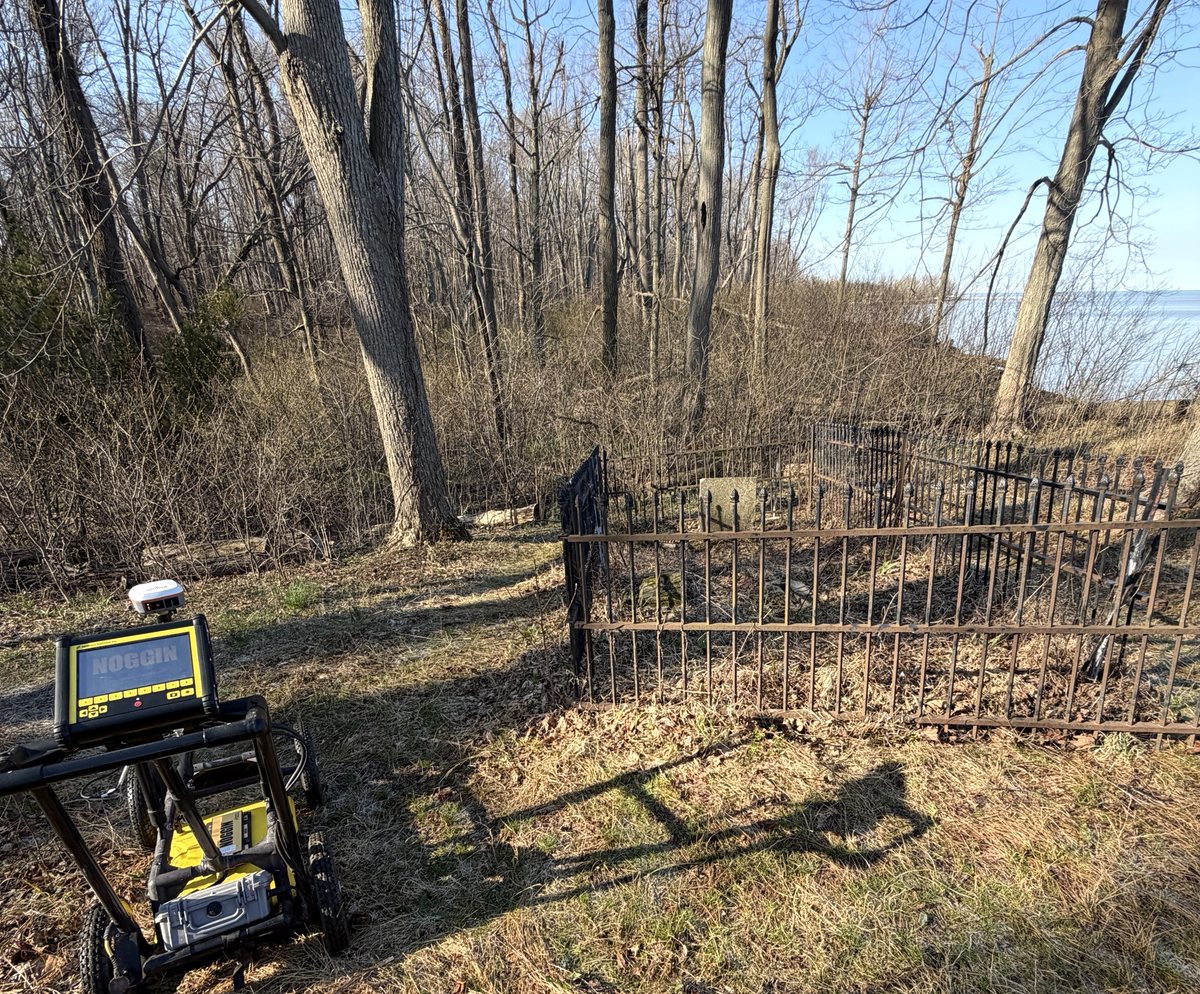
For anything that has to be defensible, we collect a grid rather than a set of wandering lines — orthogonal passes at a fixed spacing, positioned to real control. That supports time-slicing, where the 3D volume is cut horizontally at successive depths so a plan of targets emerges instead of a stack of profiles somebody has to interpret for you.
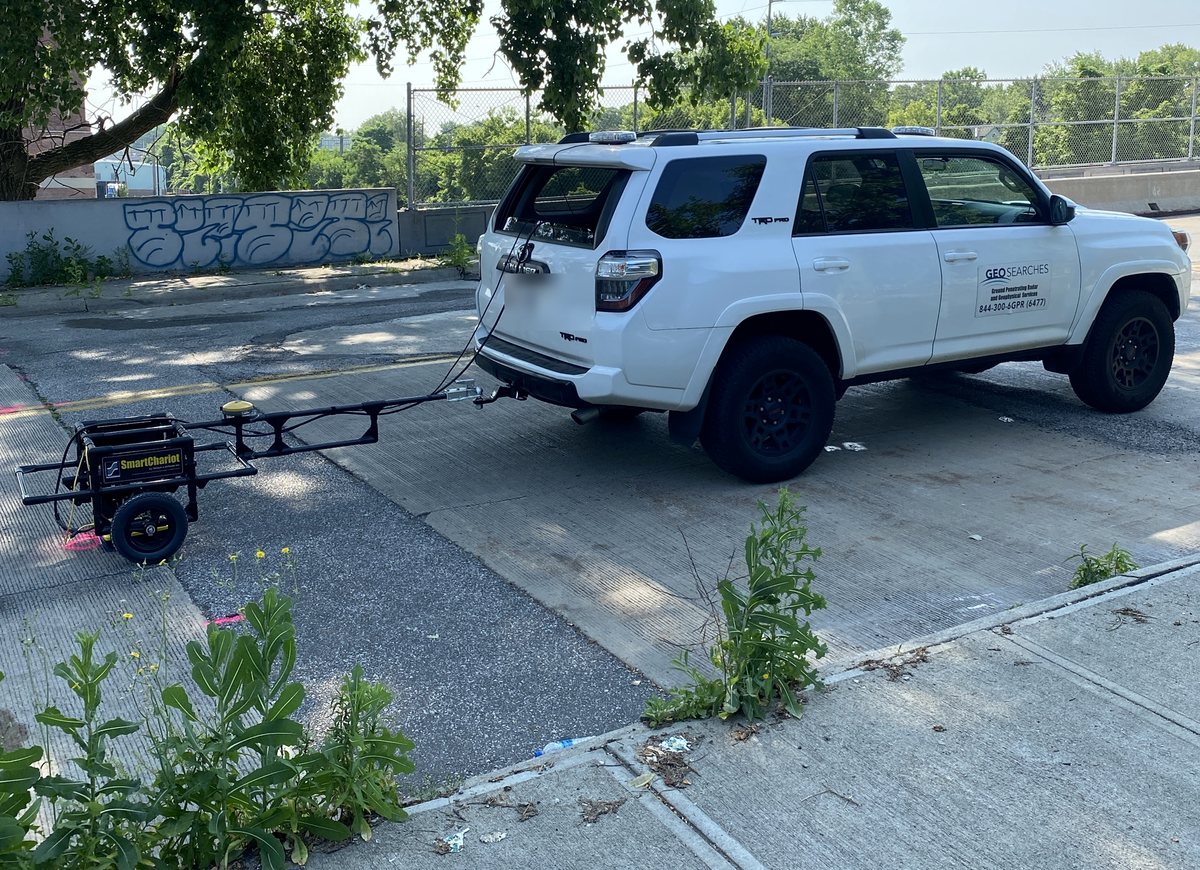
On roads, decks and runways we tow the antenna behind a vehicle at survey speed, collecting continuous lines at driving pace rather than walking them. That is what makes a structure-sized survey practical without closing the carriageway for days. On structures that becomes a bridge deck condition survey, where the strength of the reflection off the top mat of steel maps where the concrete is deteriorating.
Equipment and capability
- 1.6 – 2.6 GHz concrete antennas
- 400 MHz utility antennas
- 100 – 200 MHz deep antennas
- Vehicle-towed antenna for roads, decks and runways
- 3D grid collection and time-slicing
- GNSS and robotic total station positioning
What you receive
Marked-up findings on site in paint or chalk where the work is immediate, and a report with annotated plans, depth estimates, the radar sections themselves and a plain statement of confidence and limitation. CAD and GIS layers on request.
Ask before you commission
Tell us the target, the ground and the constraint and we will say whether this method answers it, whether it needs a second method alongside, or whether something else entirely is the better route. That conversation is free and it is usually short.
Where we have run it
Radar is the method behind most of the work we are known for. Three jobs, none of them routine, all of them public: